
Loading...
Postulate is the best way to take and share notes for classes, research, and other learning.
Designing a Space-Based Solar Power Structure (Research Notes)
 Caitlyn Coloma
The following post introduces the preliminary design for a space-based solar spacecraft structure as presented in the 2016 paper "Ultralight Structures for Space Solar Power Satellites" (citation below) and is not my own work.
Arya, M., Lee, N. and Pellegrino, S. (2016). Ultralight Structures for Space Solar Power Satellites. SciTech 2016, San Diego, AIAA-2016-1950
Background on Space-based Solar Structures
Early concepts feature conventional structures like trusses, necessitating in-space assembly by humans and/or robots. Notably, photovoltaic and power transmission systems are separate in early concepts, and a gimbal system controls the pointing of the transmission system towards Earth.

SPS-ALPHA structure. source
SSP concepts evolved towards modularity (like the robotically assembled SPS-ALPHA) and lightness while combining PV and WTP technologies into the same structures (like the gravity-tethered phase array JAXA plate). The gimbal system for beaming power back towards Earth is replaced by phased array beam steering, electronically controlling many individual beams so they interfere in the desired direction of a receiver.
Packaging Techniques for Flexible Spacecraft Structures
Solar array membranes with large areas but small thicknesses need to be packaged into launch vehicles. Efficient packaging means packaging with only minimal volume gaps in the folded package, packaging without exceeding the yield stress of the membrane, and ability to deploy the membrane to a flat state with minimal edge forces (Arya, Lee & Pellegrino 2015).
The 7.5 micrometer-thick, 14 m x 14 m IKAROS solar sail was packaged into a 1.6 m diameter using crease folding and wrapping (pictured below). The presented structure similarly folds and wraps, instead using slip folding for thicker array modules.

Adding Concentrators to Photovoltaic Systems
Instead of increasing the area of photovoltaics panels to capture more power, lightweight optical concentrator elements can be used to increase the power of minimally sized PV panels.
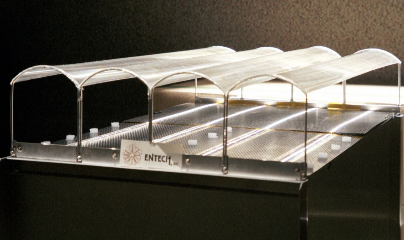
SCARLET solar array in Deep Space 1 mission used arched Fresnel lenses as concentrators with a concentration factor of 8
The Stretched Lens Solar Array used lighter and more flexible Fresnel lenses (pictured above). It is also lighter due to a composite frame supporting PV cells instead of SCARLET's honeycomb structure.
The FAST solar array used reflective linear concentrators with a concentration factor of 12.5
Optimizing Design
The proposed ultralight structure is comprised of a multifunctional tile module, a numerical model for optimizing structure, and slipping fold packaging.The optimal design is found in terms of diagonal cord tension and strip bending stiffness.
the optimal structural design is found to exist at k = 20 (i.e. 20 strips of 1.5 m width in a single quadrant), diagonal cord tension T = 3.84 N and strip bending stiffness (EI) strip = 10.78 N m. The mass of this optimal 60 m × 60 m structure is found to be 368.89 kg, leading to an overall areal density of 102.47 g m−2
Multifunctional tiles

Tiles measuring 10 cm x 10 cm act dually to generate and transmit power, while only being ~3 cm thick and having the ability to flatten for packaging. Each tile generates power through 5 parabolic concentrators that focus sunlight onto thin-film photovoltaics. Each tile is capable of transmitting its own power into a microwave signal via an integrated circuit and antenna which are housed in the tile's ground layer.
The concentrators are what give the tile its operational volume. Carbon fiber springs connect the concentrators to the tile's ground layer and allow the concentrators to elastically flatten for packaging.
Structural Framework & Numerical Modeling
Each multifunctional tile operates independently but is ultimately a part of a single, flexible structure. Many tiles make up strips of equal width, which make up concentric squares, which are held together by tensioned cords and rigid booms that run along the diagonals of the concentric squares.

A numerical model created in MATLAB is used to optimize the structure in the context of loads the structure might experience and the structure's power delivery performance.
The loading case aims to study the behavior of the structure in response to the forces acting on it (loads). The structure is expected to experience dynamic (high acceleration) loads from actuators that control the orientation of the structure in space, known as attitude control, and quasistatic (slowly accelerating) loads mostly from solar radiation pressure. Vibrations and forces from attitude control actuators are said to be negligible for the initial modeling.
The performance case aims to study how the behavior of the structure affects the desired power delivery of the tiles, which is quantified by specific concentrated power, the total power concentrated on to PV cells divided by the total mass. The angle at which sunlight hits the tile's concentrators, and in turn, the angle of deviation of any one tile from the overall planar structure, is studied for its effect on specific concentrated power.
The concentrators of each tile are designed to all be parallel in this study since it is found that the concentrators are more sensitive to the component of incident sunlight that is in the plane concentration.
The study is conducted assuming the structure is facing the sun.
Increased diagonal cord tension initially stiffens the spacecraft; after a certain point, however, increased compression in the boom reduces its effective bending stiffness, resulting in greater deflections. Increasing the strip bending stiffness also results in initial increases in specific concentrated power, but after a certain point, the mass growth due to larger TRAC boom cross-sections outpaces the growth in collected power from lower deflections.
Slipping Fold Packaging
Slipping folds allow the flexible membrane structure, i.e. tile strips, to both rotate around and translate along the axis of the fold, rather than creasing.

Parallel slipping folds achieve packaging efficiencies of up to 73%. As shown in the figure, once folded and wrapped, packaging inefficiencies only exist from 5 areas: the center and in between each of the 4 flattened arms. While this fold-and-wrap technique isn't novel, employing slipping folds specifically is, as this type of fold prevents plastic deformation of the tile strips; i.e. they do not extend when being packaged into a cylindrical launch vehicle.
Tracing the paths that each strip takes while folding and then wrapping allows us to then calculate estimates for key packaging values: the packaged height and the packaged diameter, the packaging efficiency, and the maximum slip.
Taken together, these numerical modeling and quantities results in an optimal, but preliminary spacecraft design that is ultralight, performant, and packageable.
The final result is an ultralightweight spacecraft that measures 60 m×60 m, has a mass of 369 kg (of which 288 kg, or 78%, is the tile mass), and can package into a compact cylindrical form.