
Loading...
Postulate is the best way to take and share notes for classes, research, and other learning.
Lecture 10, 11: Z and S parameters, VNAs
 Samson Zhang
Time to generalize to two-port networks!

We're introduced to Z parameters describing how inputs on both ports affect outputs on both ports.
Z parameters
You can solve for Z parameters with this lil Thevenin thing with a dependent source in the imddle.

Specifically, drive port 1 with a current source
Another way to see this is that
Anyways -- with this setup, you can measure
Like there are Norton equivalents to Thevenin circuits, so is there a Y parameter equivalent to Z parameters. I hope it's not on the quiz.

S parameters
Z parameters are hard to find at high frequency because it's hard to make a high frequency current source, and also really hard to make a high frequency open circuit, because the open will act as a capacitance. (why? doesn't capacitance decrease with frequency?)
So instead, we define easier to measure S parameters based on ratios of incident and reflected waves, taking into account transmission line effects.

Specifically:
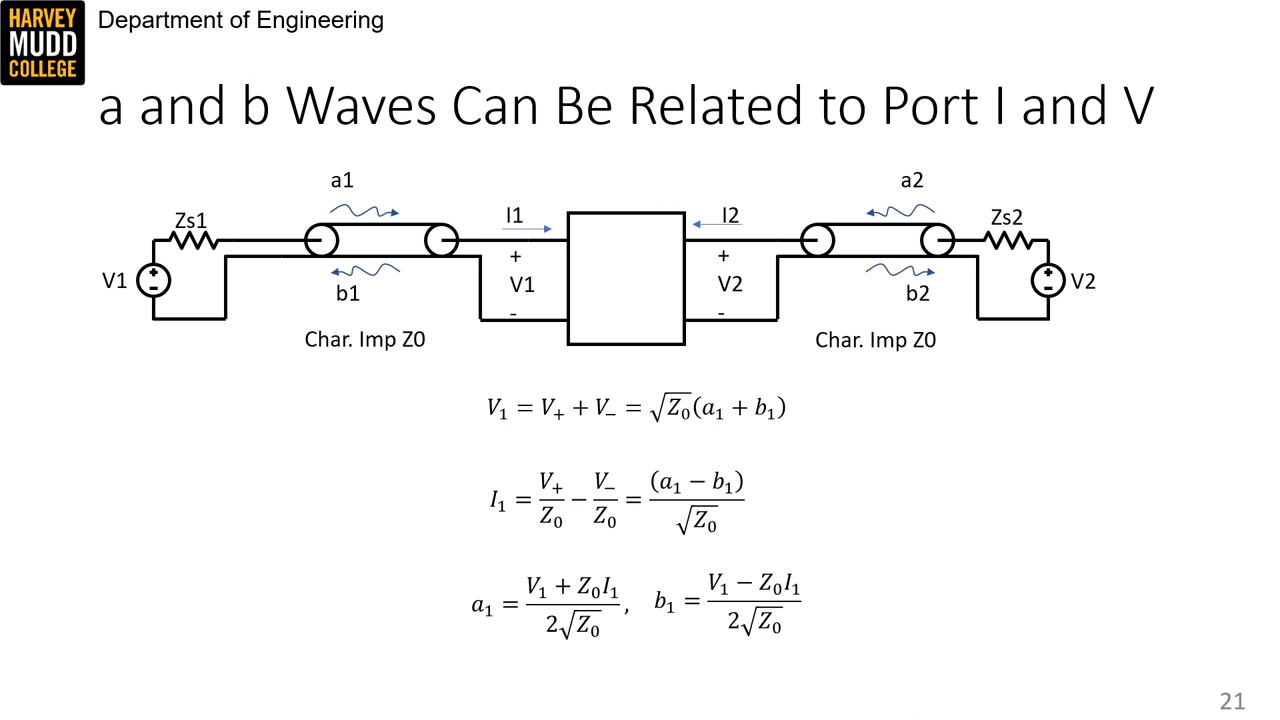
a and b definitions are a little quircky.

To convert from voltage and current (amplitude of sinusoids), use the following equations:
Which comes from this derivation:
There's also a helpful general conversion from
Here's the recap: find

Fixturing
S parameters can be measured with a vector network analyzer.
First, however, the wires attached to the device being measured -- called fixturing -- must be accounted for, i.e. the reference planes moved to the end of the wire instead of between the wire and the VNA port.
Specifically, transmission lines will add some phase

Doing a frequency sweep of each side terminated in a short is one way to determine

A through termination can be used to account for the frequency response of each port, combined

Directional couplers and VNAs
How does a VNA actually measure forward and reverse waves? With a directional coupler:

Signal going into input goes to the through port,
A VNA looks like this:

The above slide shows errors that arise if
Source mismatch can be calibrated for with an open termination, while finite directivity can be calibrated for with a load. With the short and through calibrations above, these make up SOLT calibration, which can be done manually or with something called ECal.
There are different calibrations when the device is attached to a board instead of wires, such as through-reflect-line (TRL) and line-reflect-match (LRM).
Calibrations are specific to a frequency range and cable, and also sensitive to the temperature of the VNA.
Comments (loading...)
e157: radio frequency circuit design
fall 2023 class w prof. spencer