
Loading...
Postulate is the best way to take and share notes for classes, research, and other learning.
Lecture 16: radiation from antennas
 Samson Zhang
Since
In a transmission line, voltage causes an E field between the forward and reverse paths while current causes an H field. On forward propagation, as long as
If there is a reflection/standing wave, however, voltage and current -- and correspondingly, E and H -- can move out of phase.
open t line
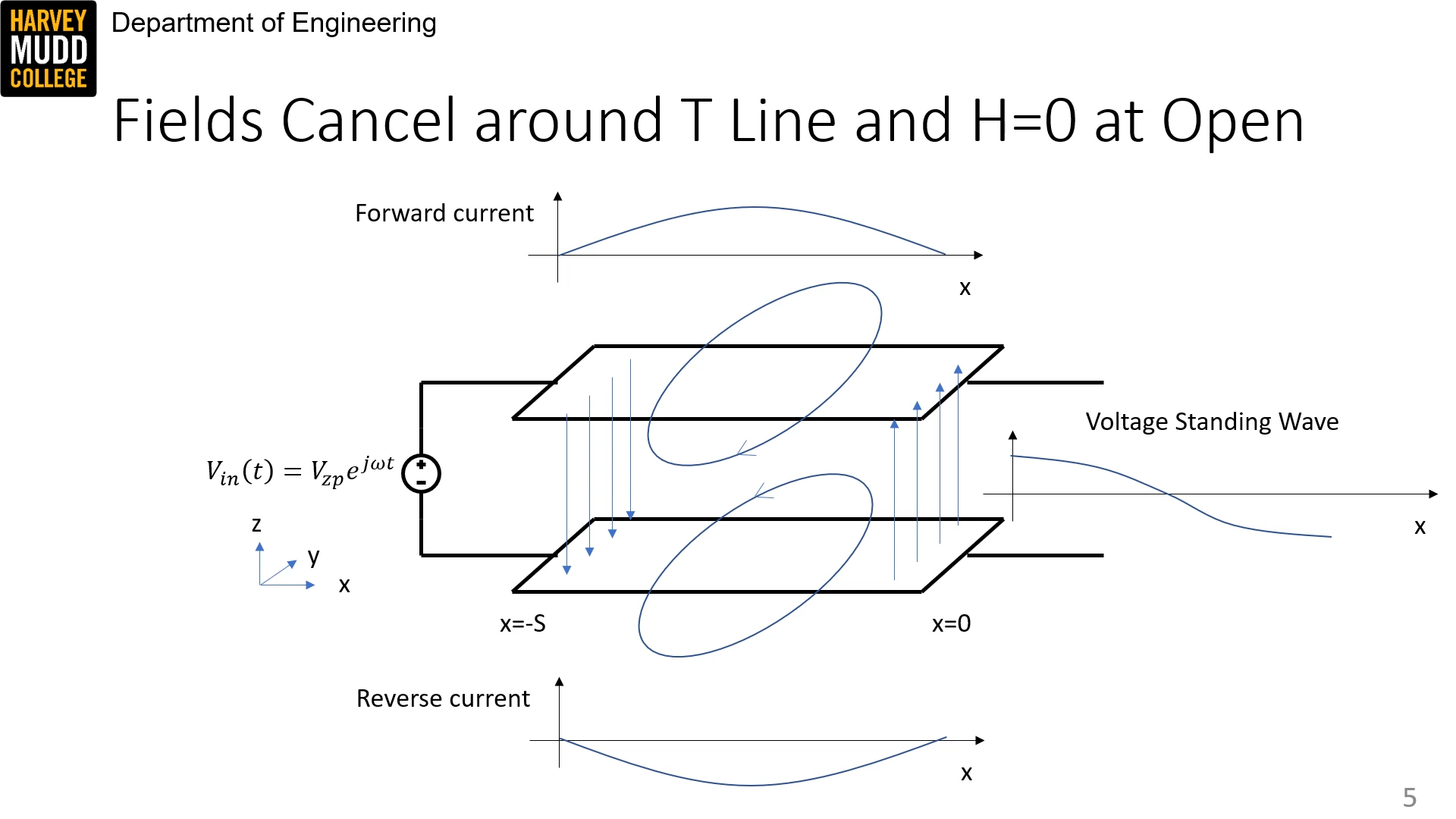
In an open t line, which is half a wavelength long, at steady state, a half wavelength current pattern is observed due to the standing wave (what does this mean?). The equal and opposite current distributions on the top and bottom cancel out fields outside of the transmission line, so there is no radiation.
short dipole antenna
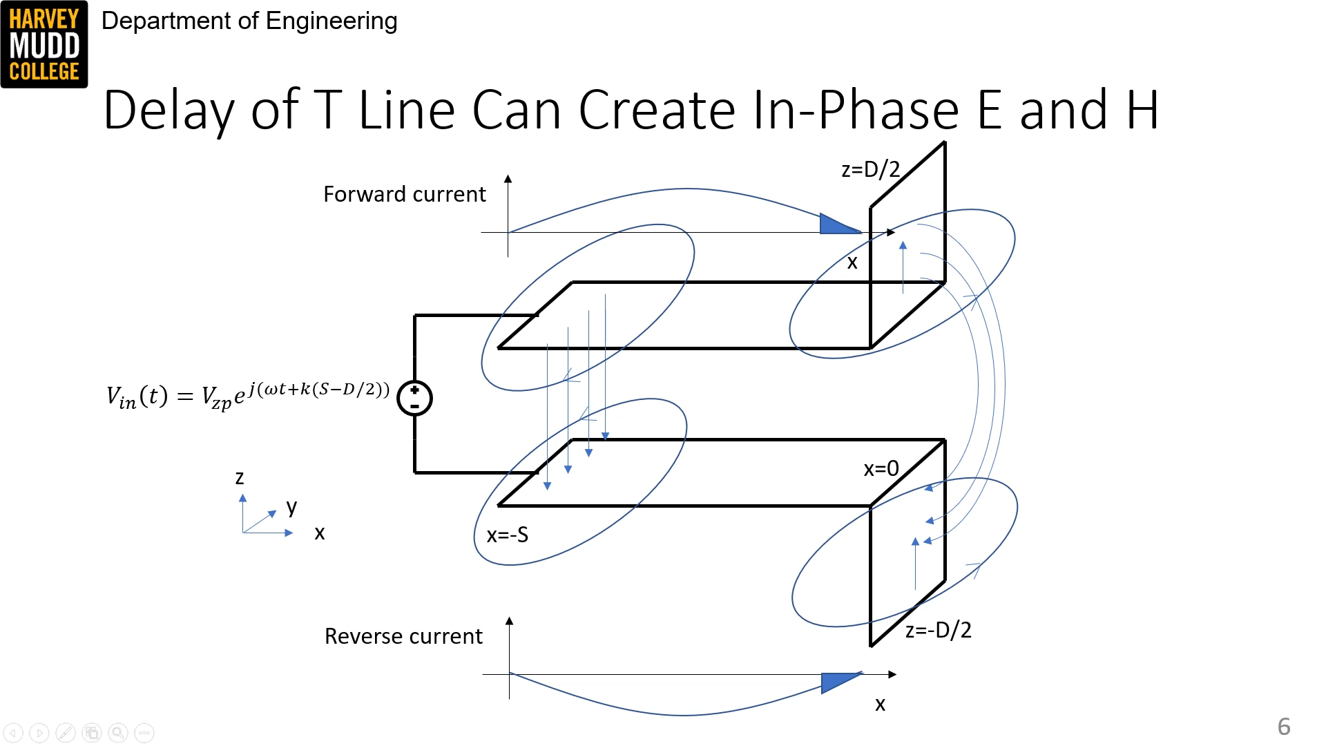
Radiation can be created by bending a length
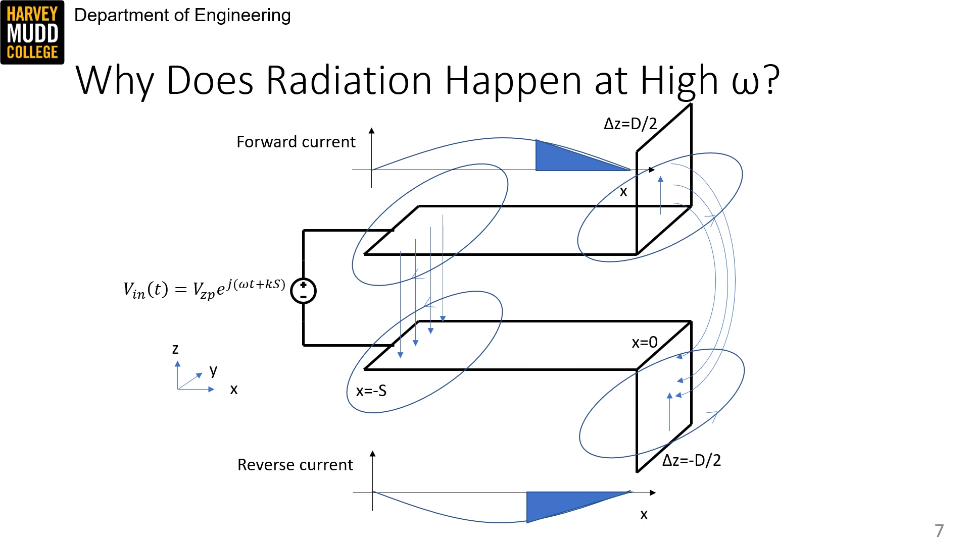
The antenna only really radiates at higher frequencies because there will be more current on the antenna.
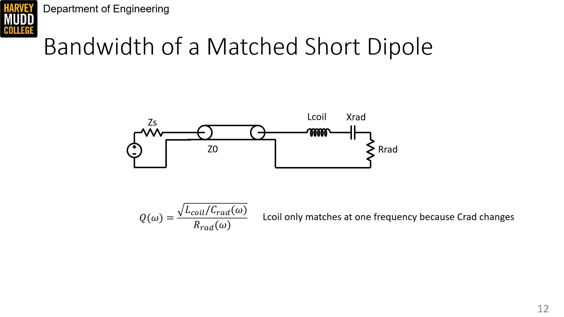
An antenna can be modeled as a resistor in series with some some reactance. The series resistance has a radiative component and a loss component.
.png)
The current distribution on a short dipole is a triangle by small angle approximation. The voltage distribution is a step (why?).
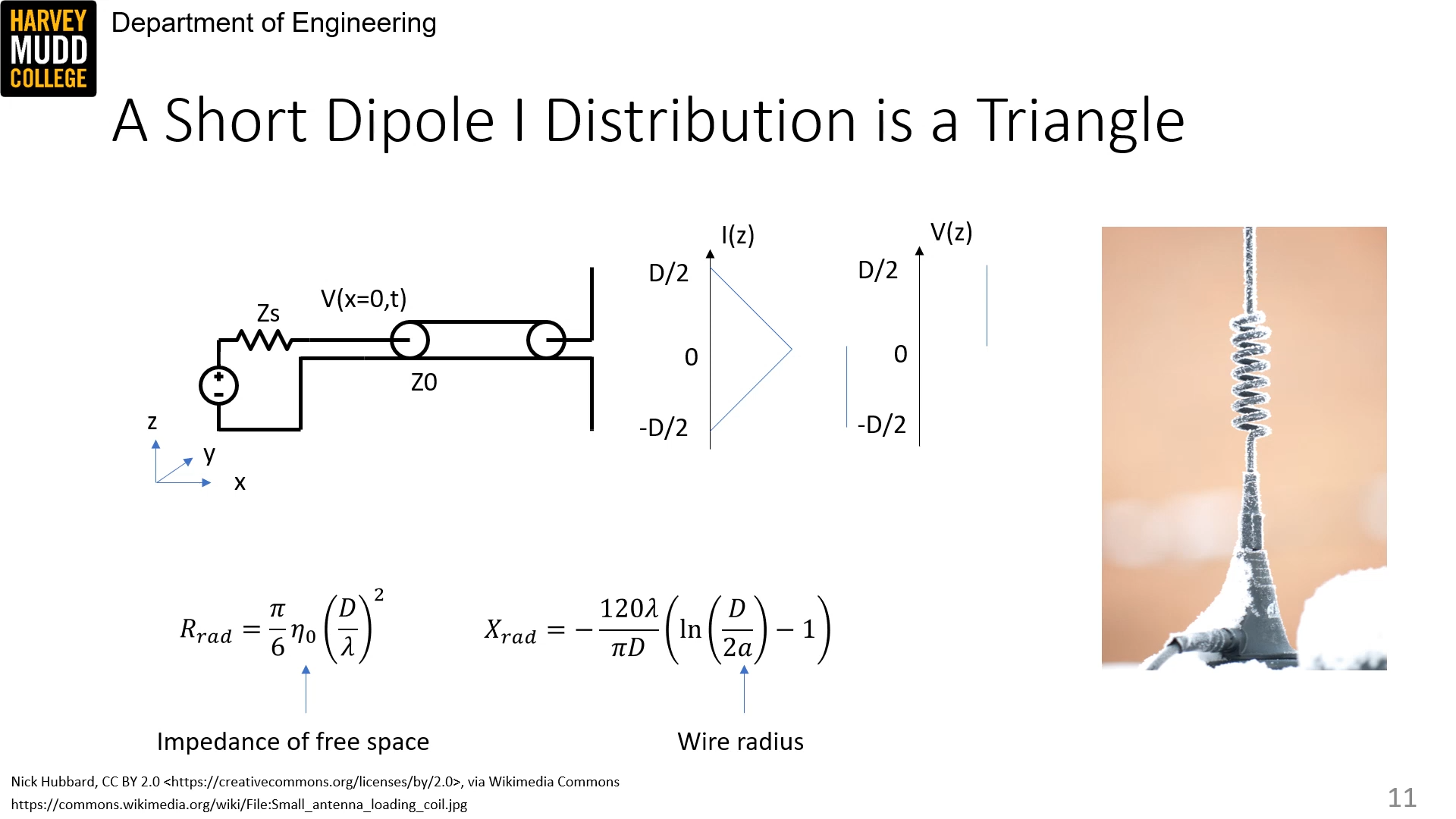
The reactance of a short dipole is negative, so it acts like a capacitor. A matching coil can therefore be created to match it, so the circuit looks like an RLC series circuit with bandwidth defined by
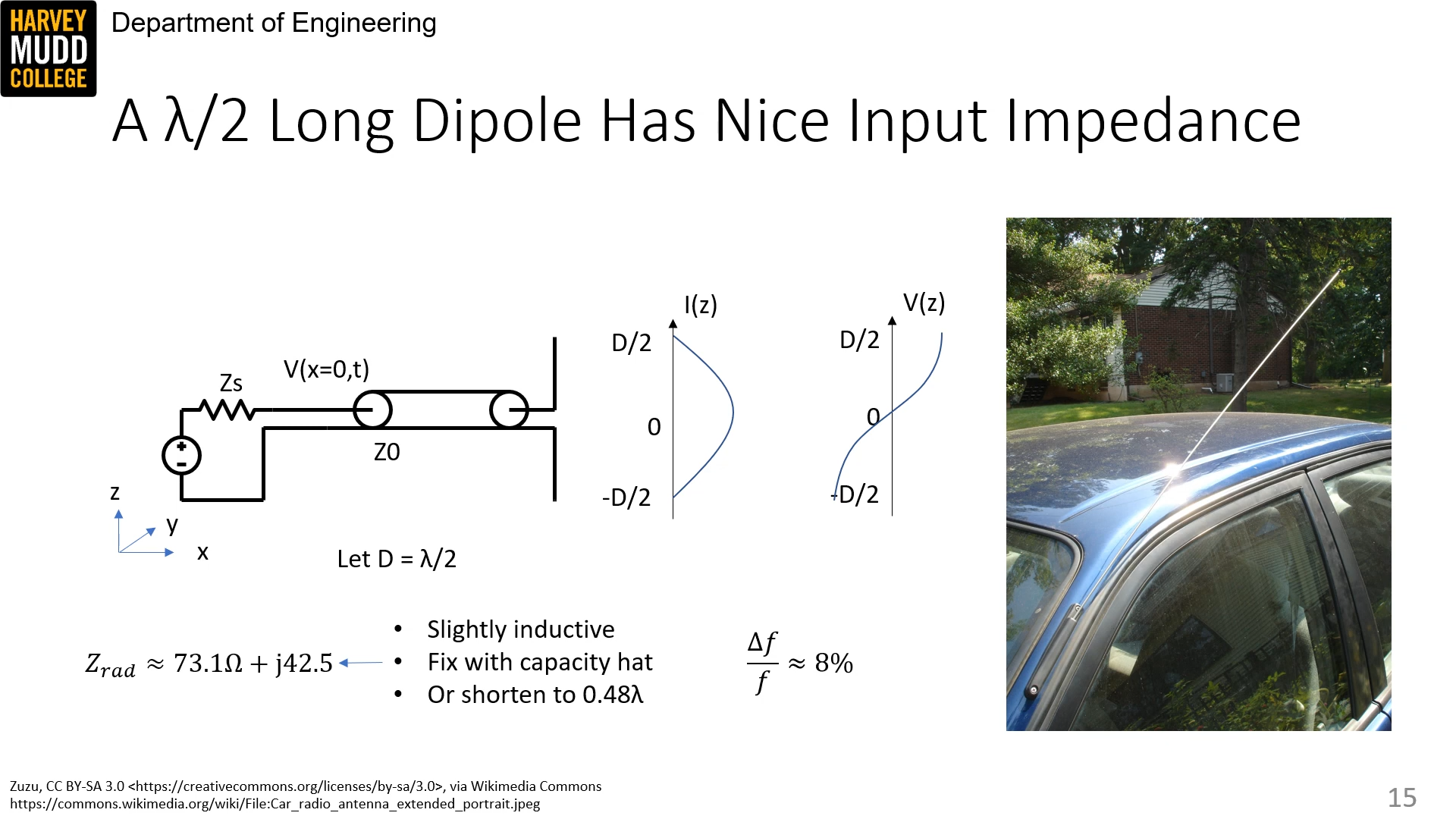
Half-wavelength dipole
Instead of
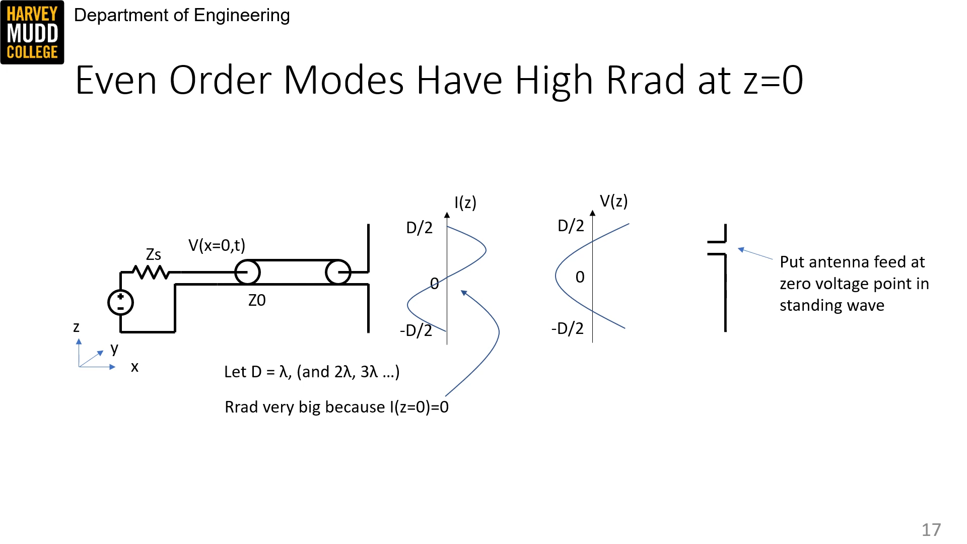
In the middle of the antenna for even modes, the driving point impedance looks infinite because
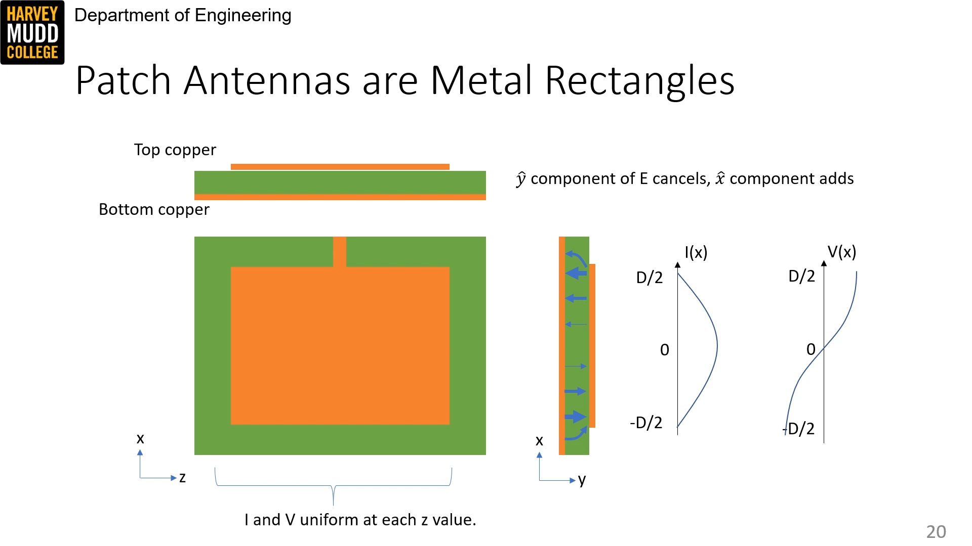
Patch antennas
A patch antenna is like many dipoles in parallel, so it has low loss but high L and C. I don't understand how it works...
The center frequency is given by
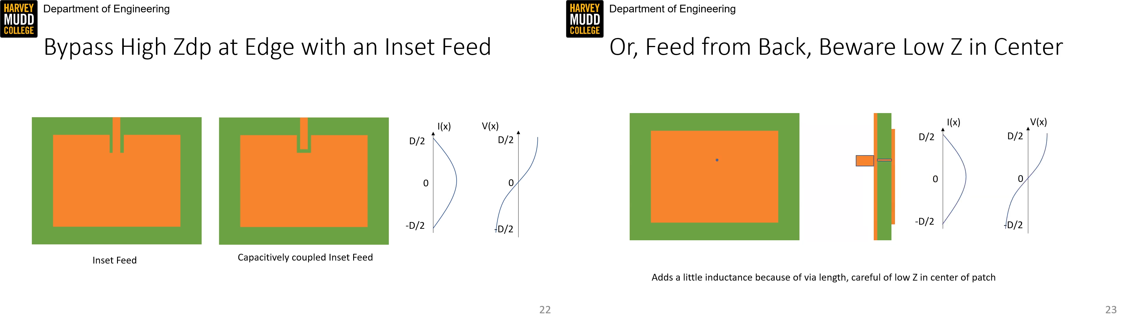
The high impedance problem can be fixed with an inset feed or poking in from the back -- though don't poke into the center, where impedance is very low.
Comments (loading...)
e157: radio frequency circuit design
fall 2023 class w prof. spencer