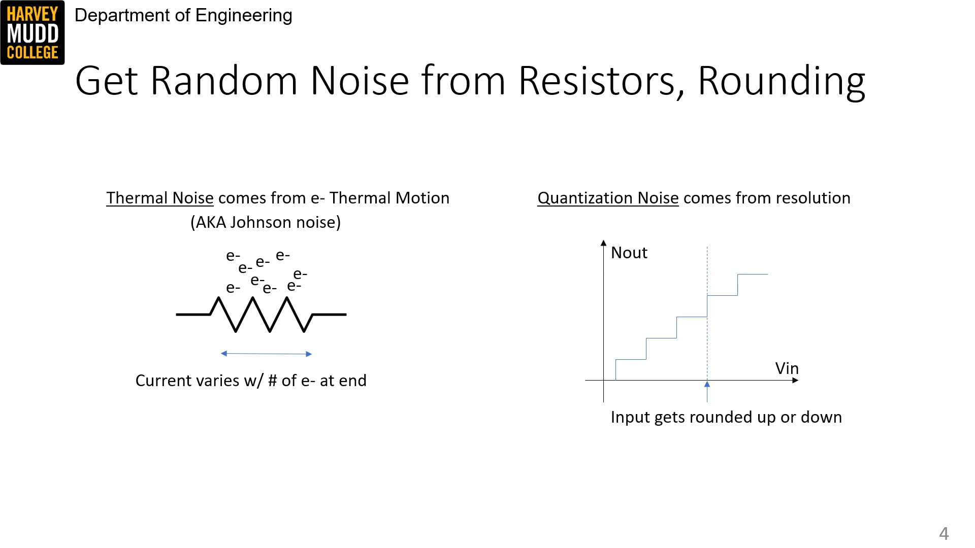
There are two kinds of noise: thermal and quantization.
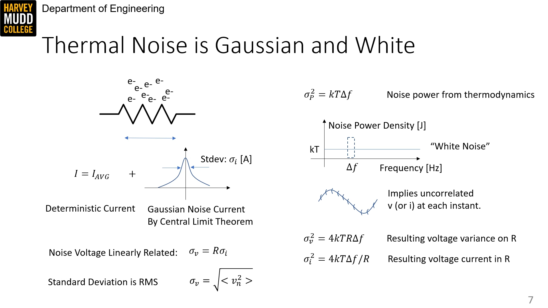
Thermal noise is Gaussian and white.
Thermodynamics yields the following equation for noise power (variance in power from thermal noise):
P_n = \sigma_P^2 = kT \Delta f
Pn=σP2=kTΔf And for voltage and current variance:
v_n^2 = \sigma_v^2 = 4kTR \Delta f \\ \\
i_n^2 = \sigma_i^2 = 4kT\Delta f/R
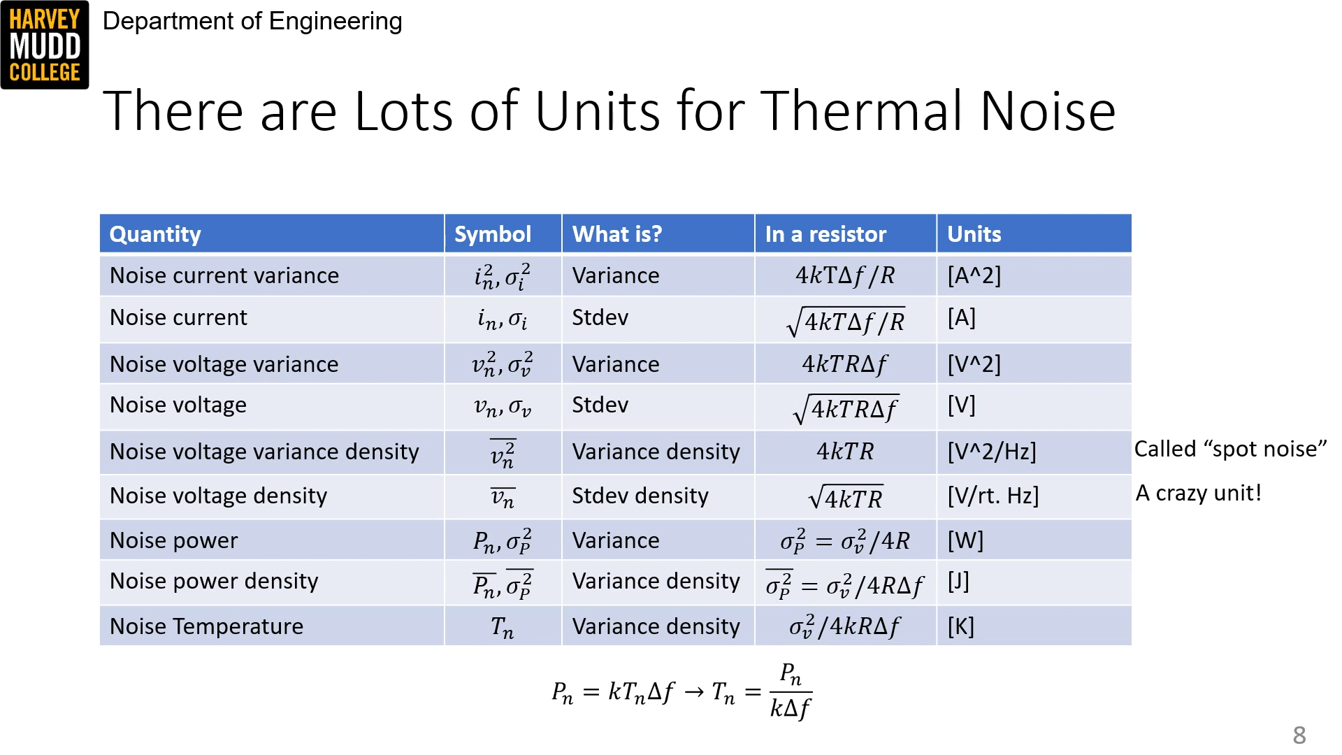
vn2=σv2=4kTRΔfin2=σi2=4kTΔf/R Thus "noise temperature" is given by:
T_n = \frac{P_n}{k \Delta f}
Tn=kΔfPn Here's a big table of symbols:
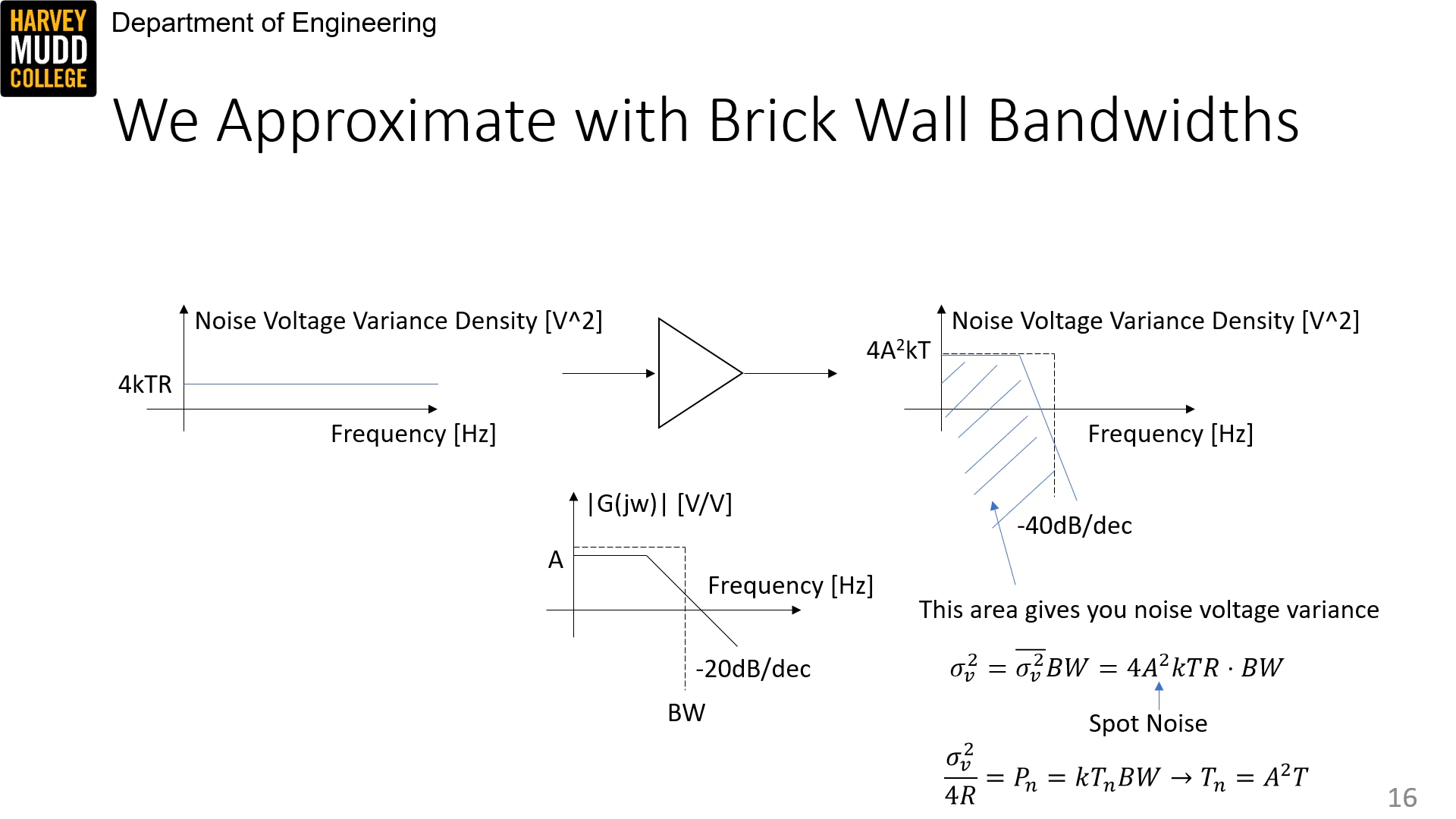
Noise variances add. They are also affected by the square gain of the transfer function (which makes sense because voltage => power). So
of voltage noise variance density before would become 4A^2 k TR 4A2kTR of noise after an amplifier with gain A. If the amplifier has -20dB/dec dropoff somewhere, the noise will have -40dB/dec dropoff.A greater bandwidth will result in a greater amount of noise, as the noise density for thermal noise is even across frequencies (white noise).
Thus:
\sigma_v^2 = \bar{\sigma_v^2} BW = 4A^2 kTR \cdot BW
σv2=σv2ˉBW=4A2kTR⋅BW and:
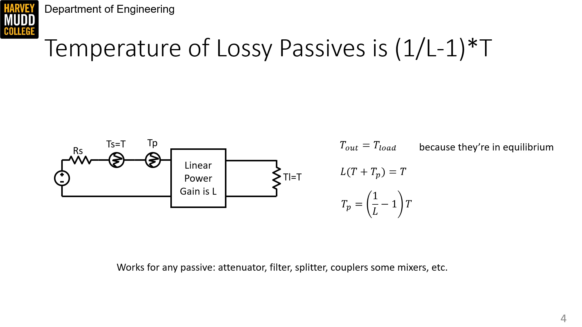
Temperature of lossy 2-port passive
The temperature of a lossy 2-port passive is:
T_p = \bigg(\frac{1}{L} - 1\bigg)T
Tp=(L1−1)T where L is the linear power gain, e.g. the insertion loss of a filter or other passive component.
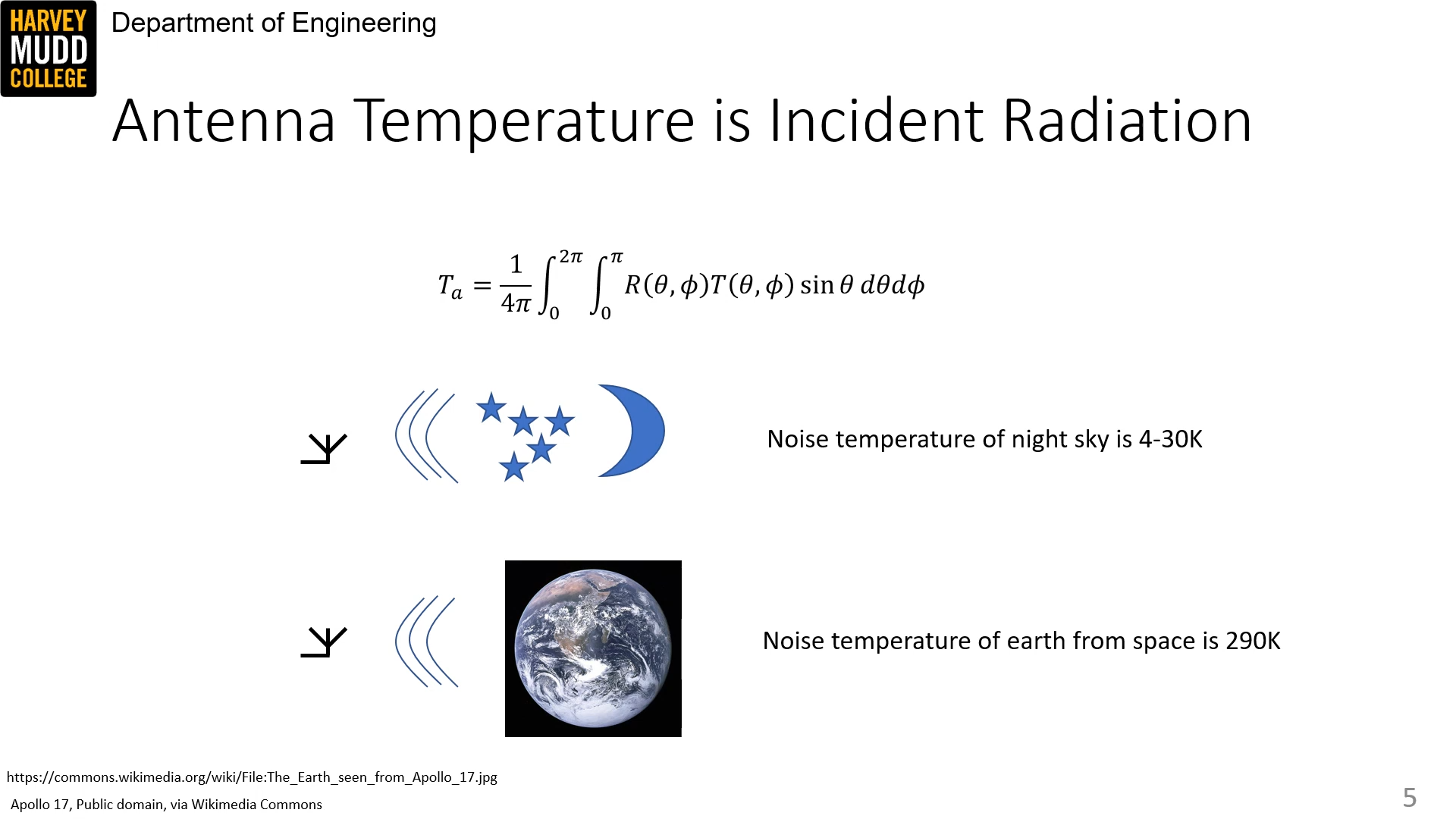
The noise temperature of an antenna is determined through a spherical integral over all the radiation incident on it.
Signal to noise ratio
Signal to noise ratio, SNR, is defined as
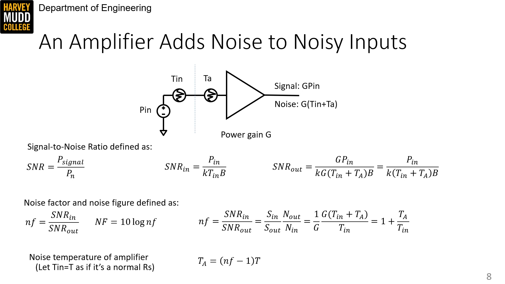
SNR = \frac{P_\text{signal}}{P_\text{in}} SNR=PinPsignal For an amplifier with some input noise
and added noise and power gain , SNR_{in} = \frac{P_{in}}{kT_{in}B} \\ \: \\
SNR_{out} = \frac{P_{in}}{k(T_{in}+T_A)B}
SNRin=kTinBPinSNRout=k(Tin+TA)BPin We also define noise factor:
nf = \frac{SNR_{in}}{SNR_{out}} = 1 + \frac{T_A}{T_{in}}, NF = 10 \log nf
nf=SNRoutSNRin=1+TinTA,NF=10lognf So amps add noise with temperature:
T_A = (nf - 1)T
TA=(nf−1)T Quantization noise
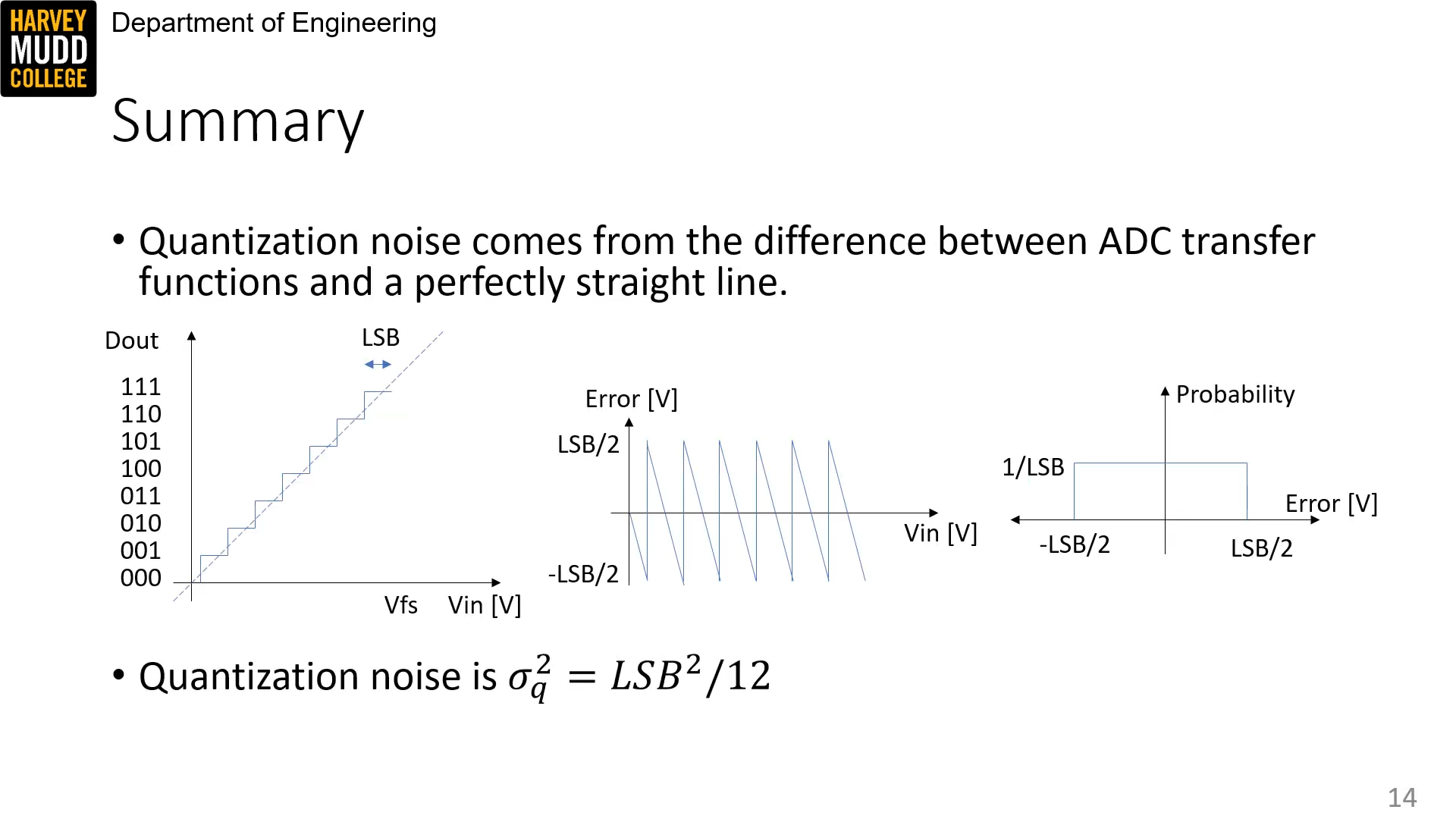
Analog digital converters add random noise with voltage noise variance:
\sigma_q^2 = LSB^2 / 12
σq2=LSB2/12 where LSB is the "least significant bit."
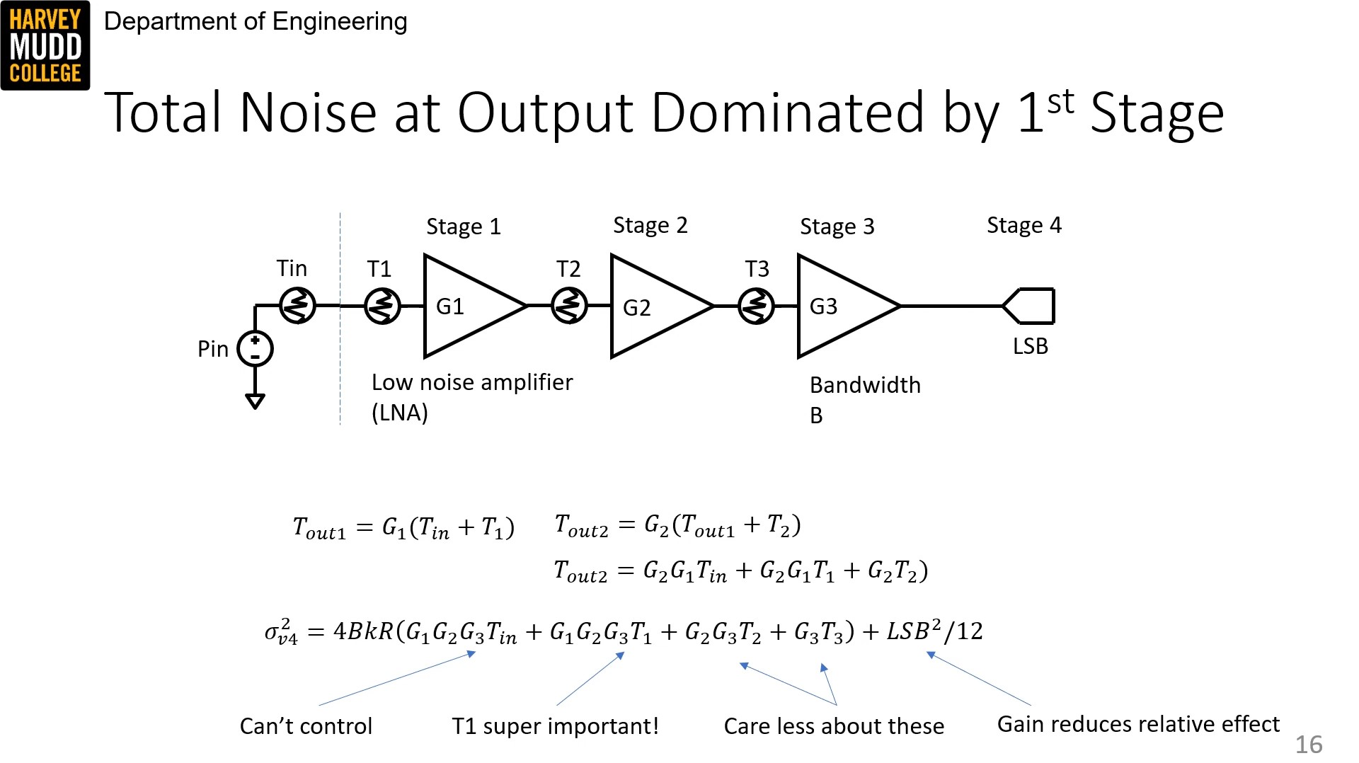
Cascading amplifiers
In a cascade of amplifiers, the noise of the first amplifier dominates over the noise of the later stages because it gets amplified.
There's a tradeoff -- more amplification reduces the relative effect of quantization noise.
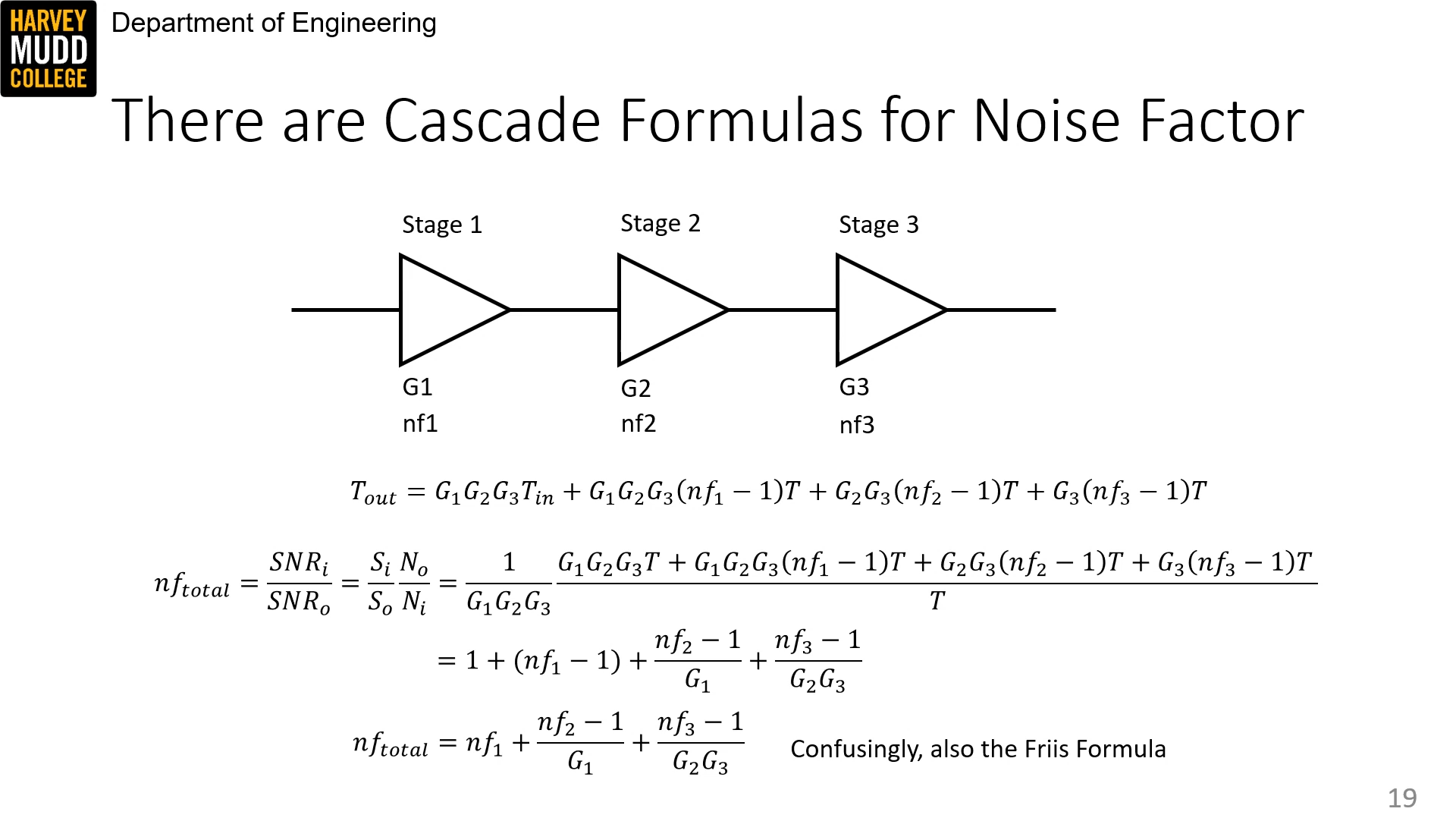
There are a few helpful formulas:
nf_{total} = nf_1 + \frac{nf_2 - 1}{G_1} + \frac{nf_3 - 1}{G_1 G_2} + ...
nftotal=nf1+G1nf2−1+G1G2nf3−1+... and, similarly:
T_{sys} = T_1 + \frac{T_2}{G_1} + \frac{T_3}{G_1 G_2}
Tsys=T1+G1T2+G1G2T3 thus, for high gain:
SNR \approx \frac{P_{in}}{k(T_{in} + T_{sys})B}
SNR≈k(Tin+Tsys)BPin 
 Samson Zhang