
Loading...
Postulate is the best way to take and share notes for classes, research, and other learning.
Lecture 23: Mixers, voltage controlled oscillators and spectrum analyzers
 Samson Zhang
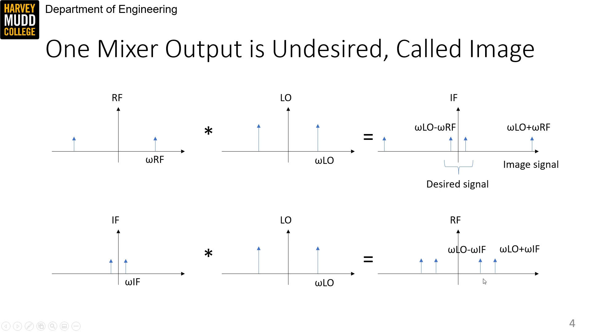
A mixer takes an input signal RF (radio frequency) and multiplies it by a signal LO (local oscillator) to get output IF (intermediate frequency). For input frequency
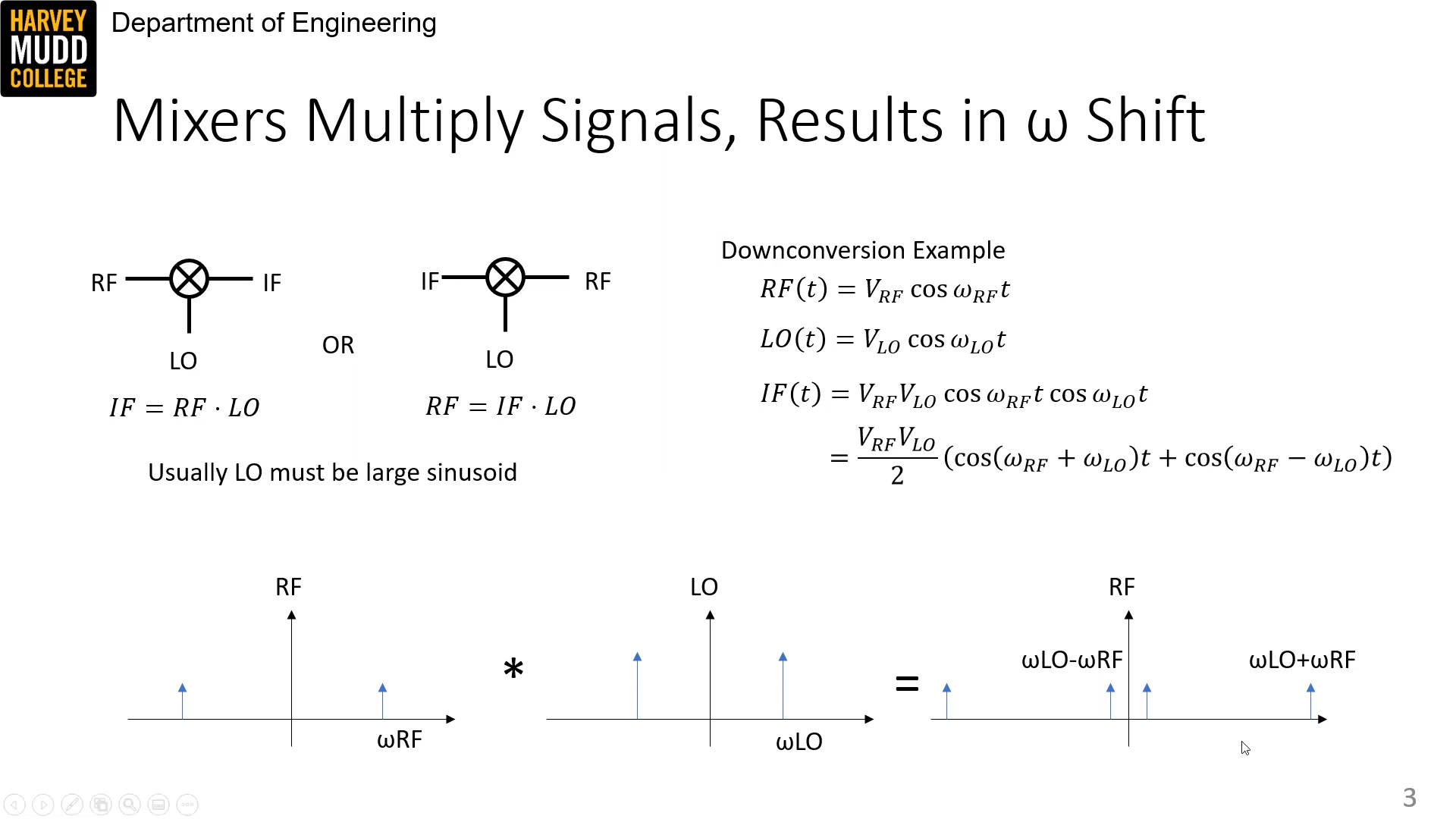
For "direct down conversion" (
For up conversion (
Mixers can be passive, made up of switches, for generally better linearity and low noise; or they can be active, made up of variable gain amplifiers, for generally higher power but also higher noise and worse linearity.
Mixer specs
Mixers are specified by conversion gain (generally negative in dB, reflecting a loss from input to output; always negative for passive mixer):
As well as isolation, which measures leakage from LO to IF and RF ports in the absence of any input signal:
They also have IIP2 and IIP3 like amplifiers, reflecting second and third order harmonic powers.
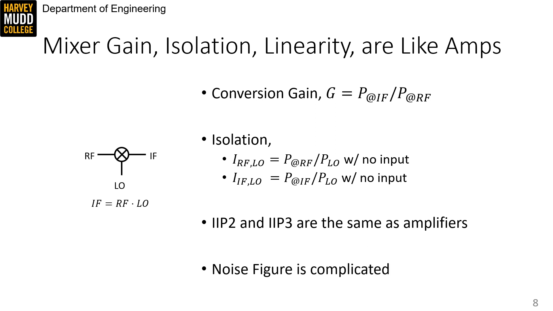
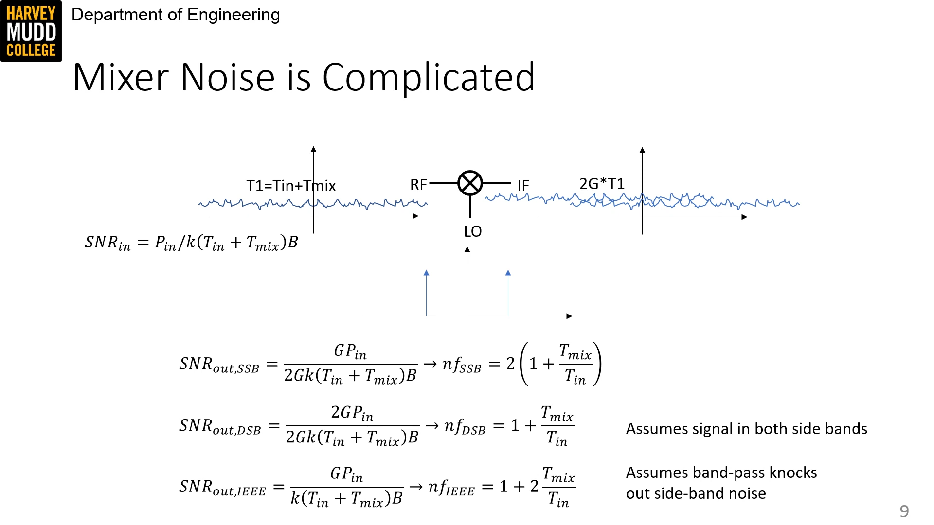
Noise is complicated apparently. There's three definitions of SNR given in the video.
Voltage controlled oscillators
VCOs are cool. They take an input Vctrl and spit out a sinusoid with frequency linear to input voltage in some range, related with a slope
 0-54 screenshot.png)
Two basic types are ring oscillators, which use unstable digital gates whose speed is controlled by input voltage, or LC oscillators, which are harder to design.
 1-56 screenshot.png)
Power detector and spectrum analyzer
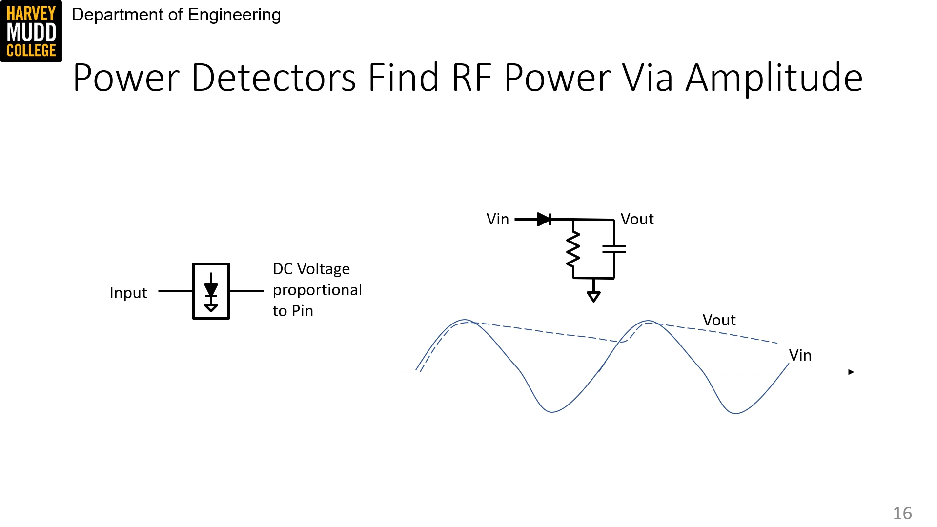
Power detectors are envelope filters, like a diode + RC filter. The cap discharge evens out the signal.
And here's an entire spectrum analyzer.
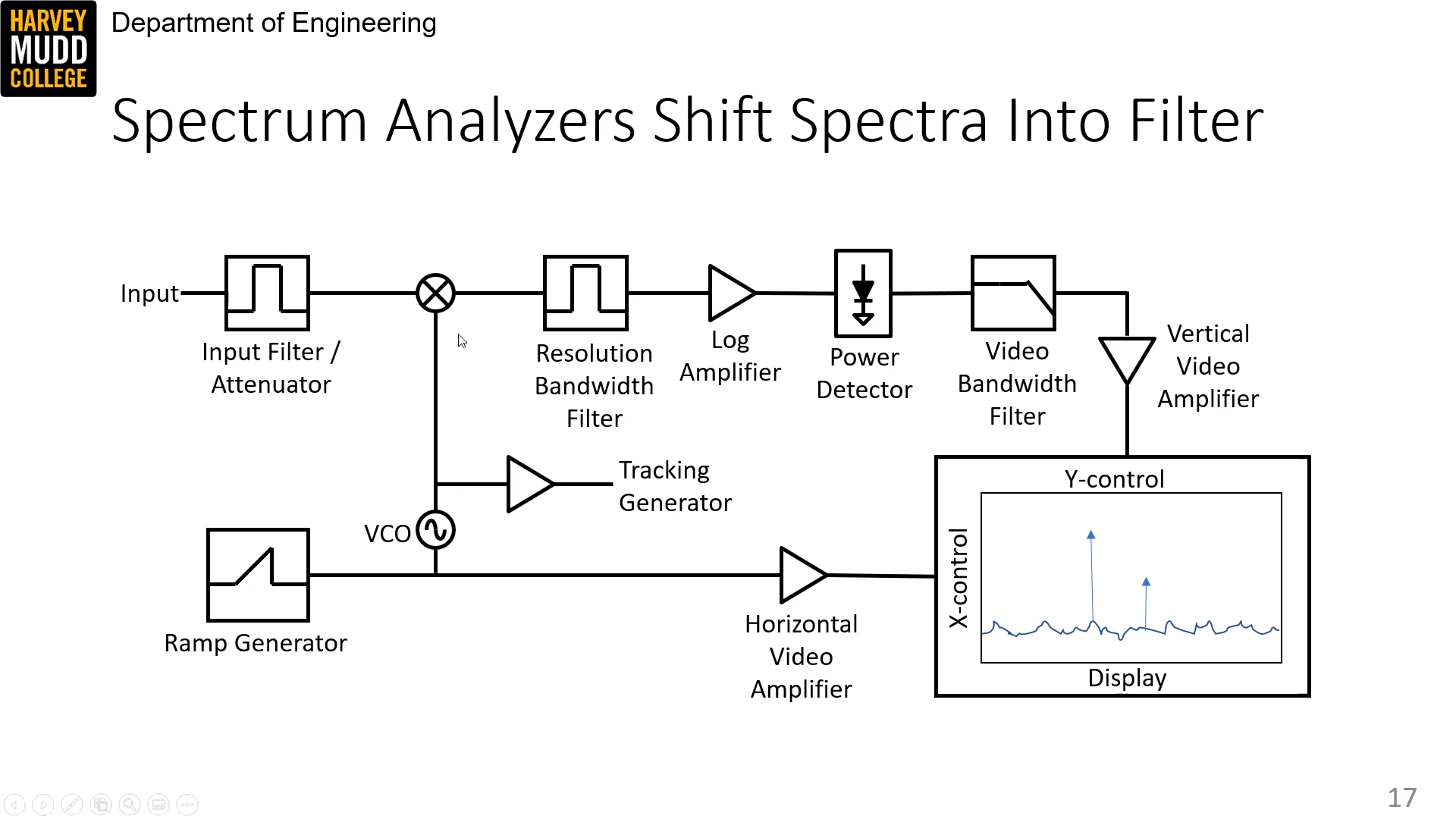
This is the part I understand:
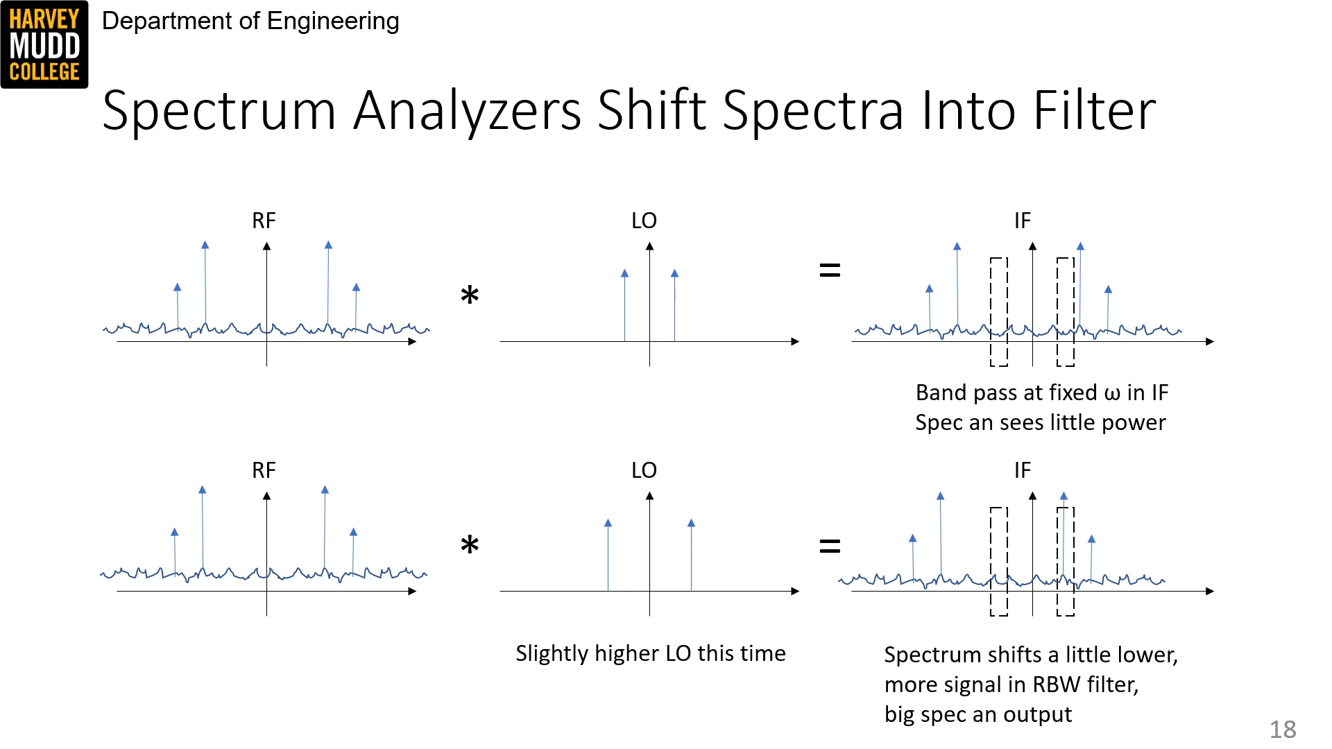
There is a tight RBW window where the power at a specific frequency is measured. Changing the LO frequency going into a mixer (with measured signal as RF) shifts the IF signal, sliding different input frequencies into the measurement window. This way, a sweep of power over frequency can be conducted.
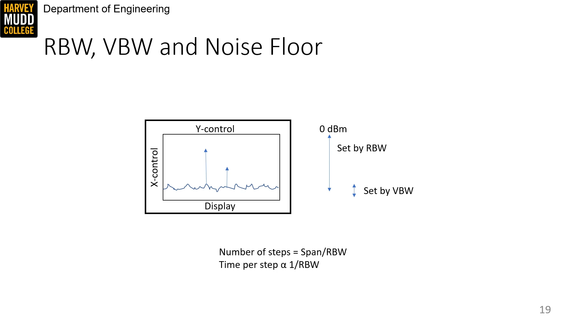
The RBW sets the noise floor because it is the narrowest bandwidth filter. That means that there is a noise floor-sweep time tradeoff.
Comments (loading...)
e157: radio frequency circuit design
fall 2023 class w prof. spencer